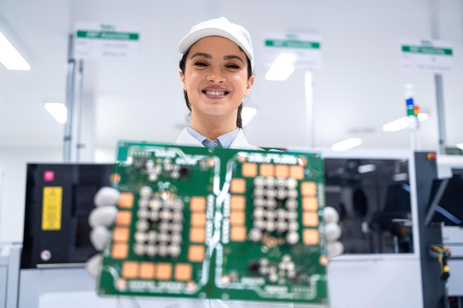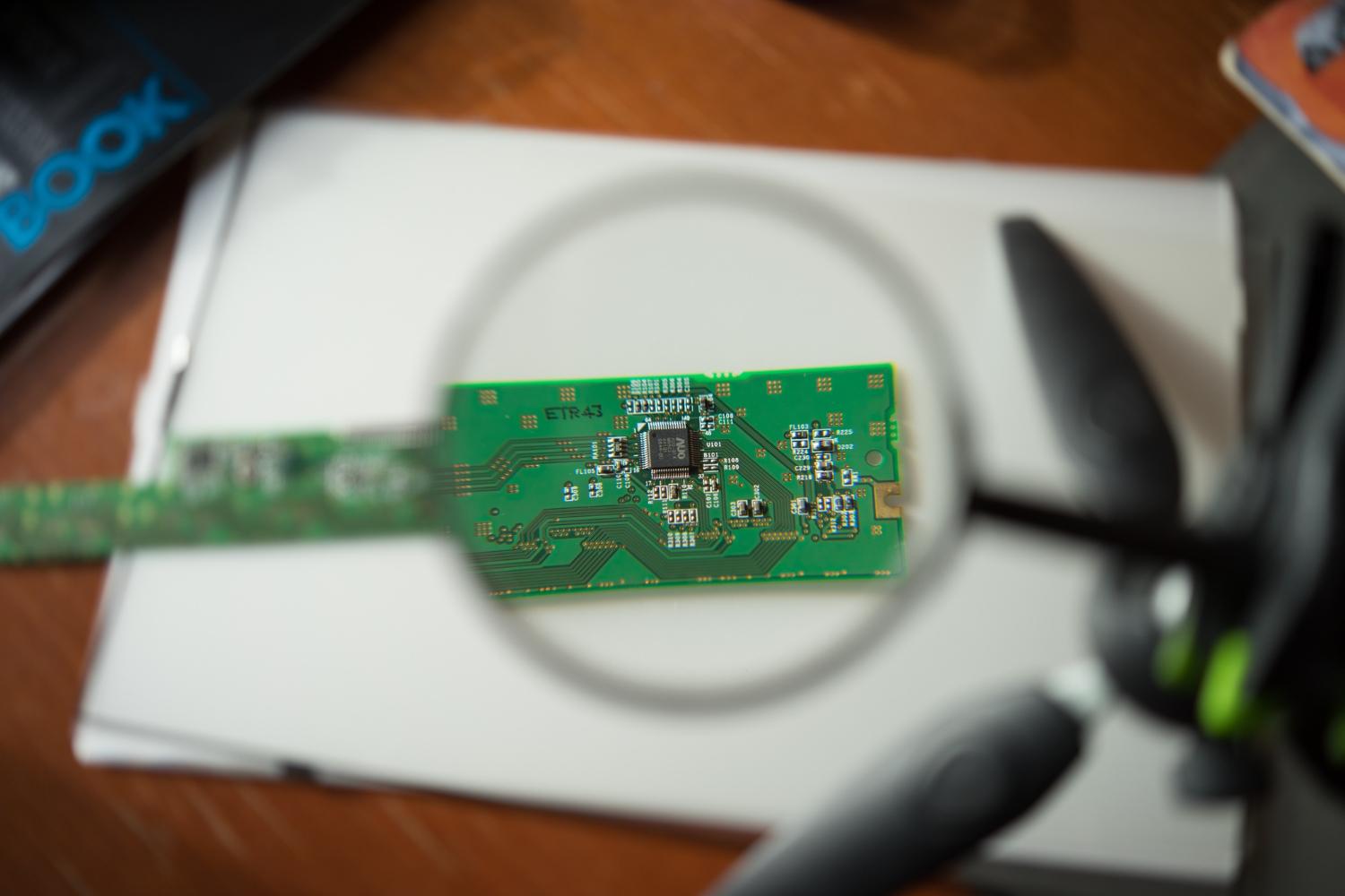
Automated optical inspection is often described as a camera checking a product. That description misses the controls that make the image useful. A camera can only record what reaches it; the production setup must present the right feature, under repeatable lighting, at a suitable scale and at the right moment.
Understanding the complete sequence helps manufacturers ask better questions during a trial. It also explains why a system that performs well on a demonstration sample may need further work when it meets normal variation on the line.
The inspection sequence from trigger to result
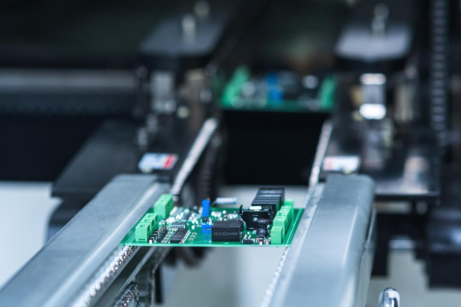
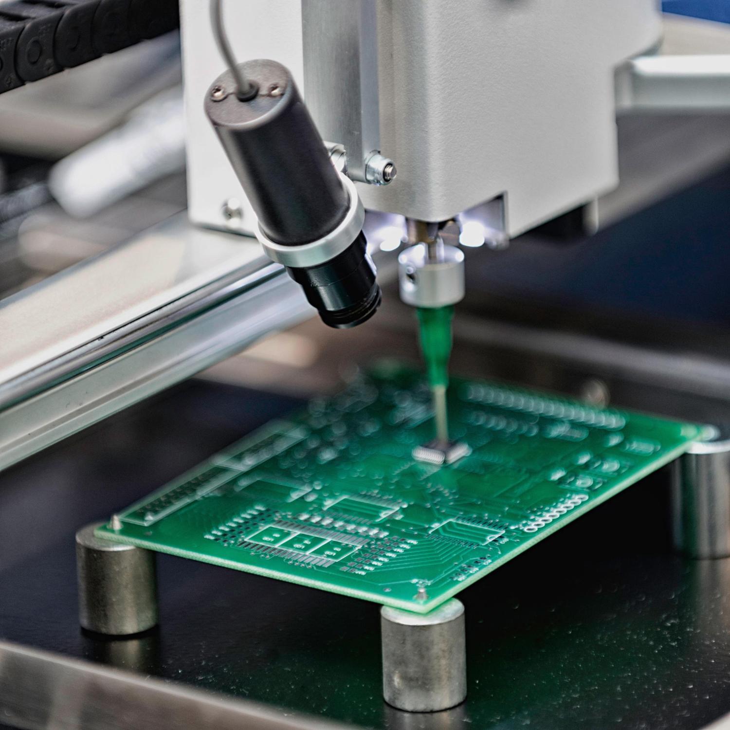
A sensor, controller, or line signal tells the station that a product is ready. The conveyor or fixture positions the item, and the system confirms the expected product or program. The camera captures one or more images while selected lights operate in a controlled sequence.
Software first locates reference points so that small placement differences do not shift every inspection region. It then examines defined areas for presence, orientation, shape, colour, markings, surface condition, position, or height. Results are compared with programmed thresholds. The station records the decision and may signal the conveyor, reject mechanism, operator, or manufacturing system.
Why lighting and optics shape what can be detected
Industrial lighting is chosen for contrast, not atmosphere. Bright-field lighting can reveal one type of surface information, while low-angle or directional light can make edges and raised features more visible. Multiple colours may separate materials that look similar under white light. Reflective solder and dark components can require different exposures or viewing directions.
Lens choice affects field of view, distortion, depth of field, and the size of a feature in pixels. A wider view covers more area but gives each small feature fewer pixels. Higher resolution can increase detail, but it also creates more image data and does not solve poor focus, vibration, glare, or hidden geometry.
Teaching acceptable variation without hiding defects
An inspection program needs a reference for what is expected. Traditional methods may compare measurements with limits, use templates, analyse edges, or classify colours and textures. Some modern tools learn patterns from labelled examples. In both cases, the training set should represent normal good variation as well as meaningful defects.
Limits that are too tight create false calls. Limits that are widened without investigation can allow defects to pass. Program development should involve quality, process, and production personnel who understand what is critical and what variation is harmless. Changes need version control and a reason, especially when several products share a line.
The broader automated optical inspection systems guide lists the production and supplier information needed before equipment selection.
Operator review turns an alarm into a quality decision
Many AOI findings are reviewed by a trained person. The interface should show the location, captured image, expected condition, measured result, and classification clearly enough for a consistent decision. Review stations need suitable screen quality, access to work instructions, and a defined method for handling uncertain cases.
Accepted and rejected findings should feed useful records. Repeated errors at one component, feeder, printer area, or time period may point to a process problem. The aim is not simply to count defects; it is to prevent recurrence and reduce the cost of downstream rework.
What to consider when validating the workflow
Test normal product variation, start-up conditions, changeovers, line stops, barcode errors, reinspection, and communication failures. Confirm what happens when the station cannot identify the product or loses a network connection. A safe response may be to stop, hold, or route the item for review rather than assume it is acceptable.
Measure cycle time with the complete image sequence and data transfer enabled. Review staffing, program creation time, backup procedures, calibration, lens and light cleaning, and spare-part needs. For deployment planning, continue with the guide to integrating AOI into a production line.
AOI works best when image acquisition, decision rules, human review, and process feedback are designed as one system. Improving only one element may move the bottleneck rather than improve inspection.
Documentation should make that chain repeatable. Keep the approved program revision, product setup, camera and light configuration, inspection limits, known exceptions, and review instructions together. When a product, material, fixture, lens, software version, or process condition changes, assess whether the inspection still represents the approved method. This discipline is less visible than a new algorithm, but it protects results from gradual drift.