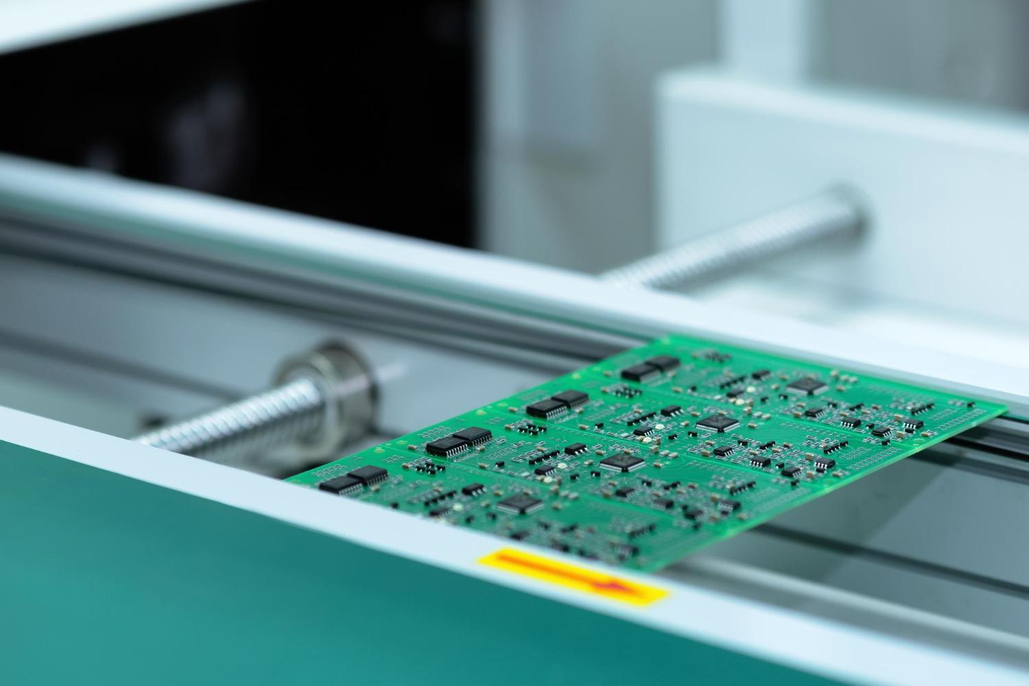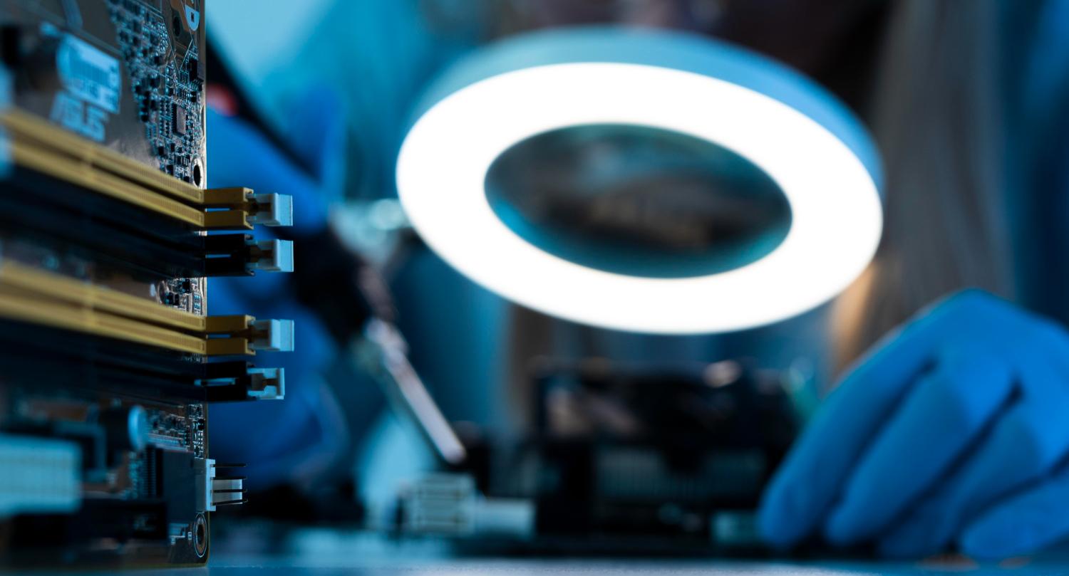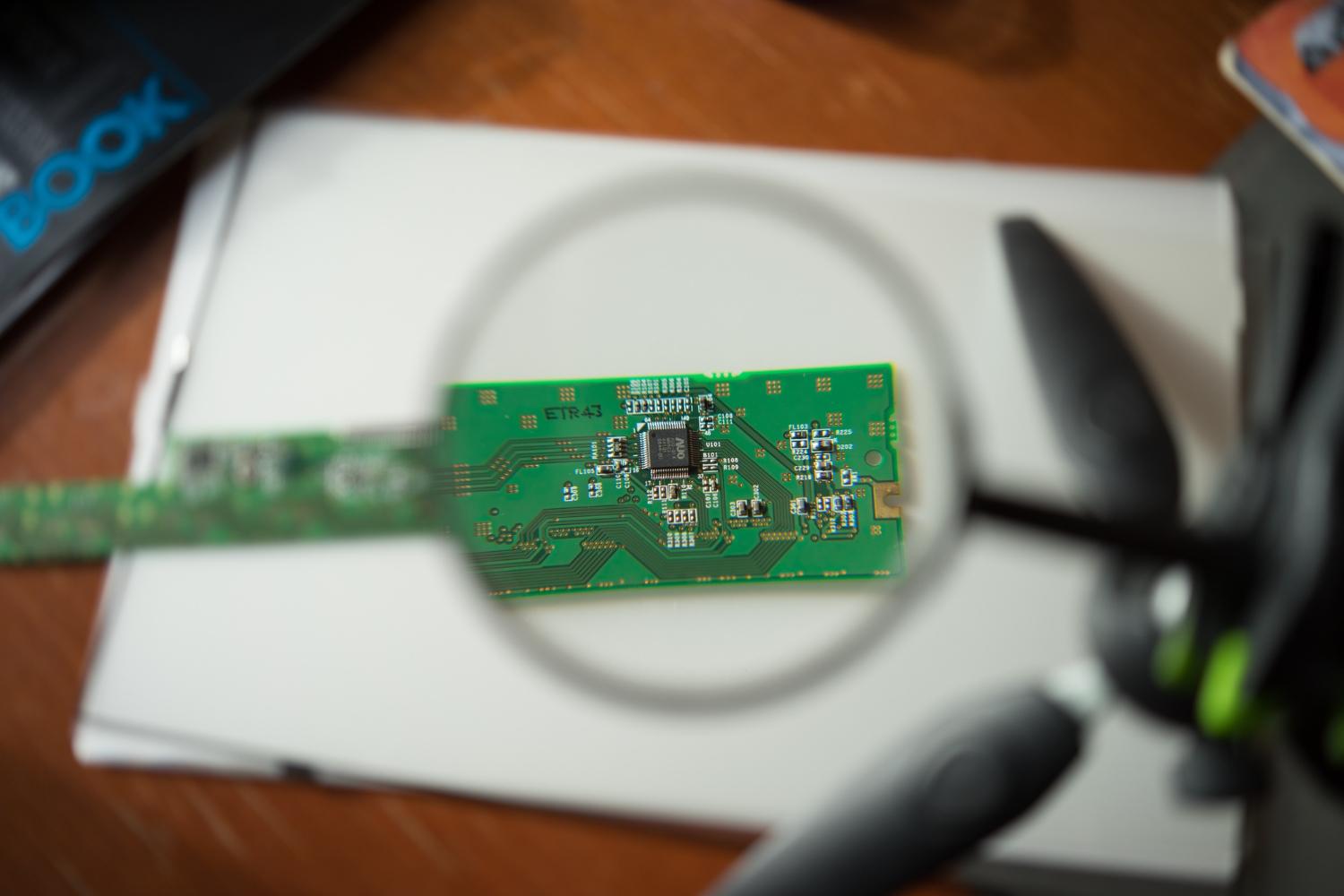
Manufacturers sometimes ask whether AOI can inspect a board as if coverage were a single percentage. A more useful question is whether the proposed system can detect each important defect under normal production conditions. Printed circuit assemblies contain varied shapes, finishes, markings, heights, and hidden interfaces, so visibility changes across the board.
A defect matrix links each risk to its process step, inspection method, acceptance rule, and reaction. This prevents a visible inspection station from being credited with checks it cannot physically perform.
Component presence, identity, and orientation
AOI can often identify missing or extra components, wrong packages, reversed polarity, rotated parts, and incorrect markings when the relevant feature is visible. Optical character recognition or pattern comparison may support code checks, although small, faint, variable, or reflective markings can reduce reliability.
Similar packages need careful validation. Two parts may share shape and colour while differing electrically. If the visible marking cannot be read consistently, barcode control, feeder verification, traceability, electrical test, or another process control may be more dependable than image classification alone.
Position and alignment checks
Inspection regions can measure component offset, rotation, lead position, and alignment with pads or board references. These checks can reveal placement drift before it causes widespread rework. Tolerances should reflect the design and process need rather than the smallest number the software can display.
Board stretch, warp, fixture variation, and reference-location errors can shift apparent positions. Good programs use suitable fiducials or alignment features and distinguish global board movement from a local placement problem.
Visible solder and surface conditions
Depending on lighting and viewing geometry, AOI may flag solder bridges, insufficient or excessive visible solder, open-looking joints, lifted leads, contamination, scratches, or damaged components. Reflective solder can change appearance with angle, so several lighting conditions or 3D measurement may be useful.
A visible fillet does not prove the complete internal joint. Inspection after different process steps also answers different questions. Pre-reflow checks can identify placement issues; post-reflow inspection observes the result after soldering. The broader guide to how AOI works explains how lighting and thresholds influence these decisions.
Conditions normal AOI may not see
Joints under bottom-terminated components, internal voids, hidden cracks, incorrect electrical values with identical appearance, firmware problems, and functional failures may not produce a visible signature. X-ray, in-circuit test, functional test, electrical measurement, process monitoring, or destructive analysis may be required.
Occlusion is another limitation. A tall connector can block a nearby feature from one camera angle. Additional views may help, but access should be demonstrated. Teams should not assume that a camera described as multi-angle has a clear path to every critical location.
Build and maintain a defect coverage plan
List known defects from design reviews, process history, returns, rework, and risk analysis. For each one, identify a representative sample, expected frequency, severity, optical signature, and required response. Use this set during acceptance testing and keep it under controlled storage where practical.
Track false accepts and false calls separately. A low alarm count can mean a stable process, but it can also mean loose limits. A high count may indicate process drift, unsuitable programming, or harmless variation. Review trends by product, location, machine, program version, and time.
Use the main automated optical inspection systems guide when comparing equipment, then review AOI versus manual inspection for checks that still benefit from human judgement. The strongest control plan assigns each method a clear purpose.
Sampling plans should not be confused with capability tests. Passing a small set once does not show that the station remains dependable across shifts, lots, suppliers, temperatures, or routine maintenance. Where defect risk justifies it, schedule periodic challenge checks and audits of accepted boards. Investigate any disagreement between AOI, downstream testing, rework findings, and customer returns.
Design information can improve the plan. Pad geometry, package data, polarity marks, keep-out areas, and expected component positions help define checks, but production images remain essential because manufactured boards include tolerances and optical effects that design files do not show. Keep the resulting evidence with the approved inspection revision so later changes can be assessed against the same basis.