Visual inspection becomes difficult when a production line handles small components, repeated patterns, tight tolerances, or a volume that leaves little time for careful manual checking. Automated optical inspection, usually shortened to AOI, uses controlled imaging and software rules to examine a product for visible differences that may indicate a defect.
The technology is widely associated with printed circuit boards and printed circuit assemblies, but the underlying approach can also support other manufacturing tasks where surfaces, dimensions, presence, position, colour, or assembly features can be assessed through images. AOI should be treated as part of a quality process rather than a machine that independently guarantees quality.
What an AOI system actually does
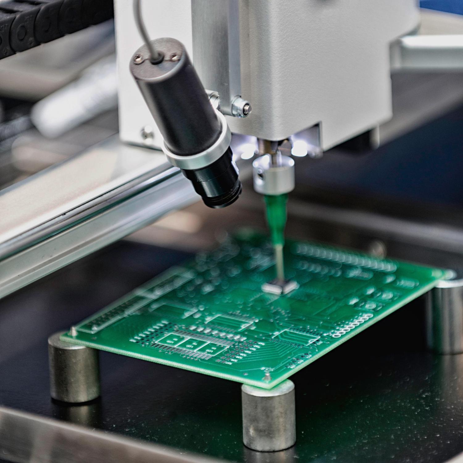
An AOI station normally combines cameras, lenses, lighting, product handling, image-processing software, inspection programs, and an operator interface. The system captures images under repeatable conditions and compares measured features with an approved model, programmed limits, or learned examples. It then records a pass result or flags an item for review.
In electronics manufacturing, checks may cover component presence, orientation, polarity, alignment, solder appearance, contamination, or visible damage. The exact capability depends on camera resolution, viewing angle, illumination, board access, component geometry, and how the inspection rules were developed. A general statement that a machine “finds defects” is not enough; the intended defect list should be written down.
How automated inspection moves from image to decision
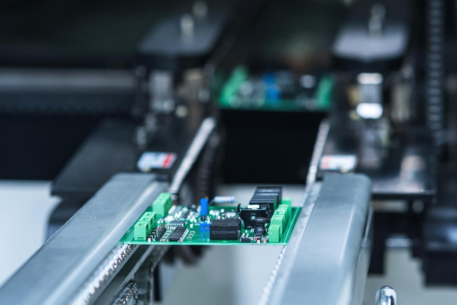
The first step is stable presentation. A board or part must arrive at a known position, remain sufficiently still, and be visible to the optical arrangement. Lighting is selected to make relevant features stand out. Different colours, angles, or patterns of light may reveal edges, height changes, reflective solder, markings, or surface damage in different ways.
The camera converts the scene into image data. Software locates inspection regions and evaluates features such as contrast, shape, position, size, texture, or height. A result outside the programmed tolerance is classified or sent to an operator. The production team then decides whether to accept, rework, investigate, or stop the process.
That final response matters. Inspection data has more value when it helps identify a recurring placement, printing, handling, or material issue. The guide to how AOI inspection works follows this sequence in more detail.
When manufacturers consider AOI
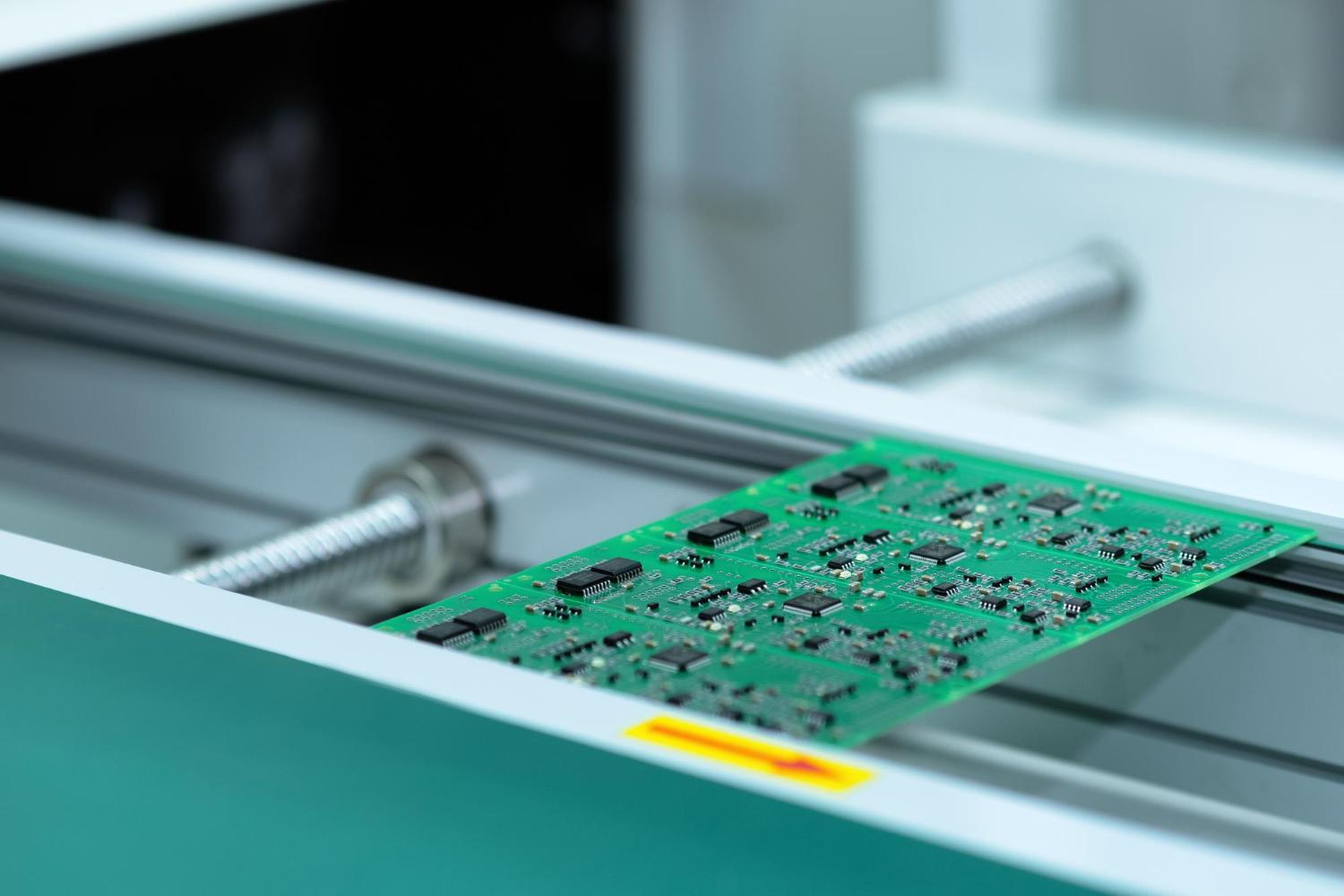
AOI is useful when visual characteristics are important, products repeat often enough to justify programming, and inspection speed or traceability is difficult to achieve manually. It may be placed after solder-paste printing, component placement, reflow, assembly, or another process where an early check can prevent defects from moving downstream.
It is not automatically the right solution for every line. A low-volume, frequently changing product may require more engineering effort than expected. Hidden joints, internal conditions, and defects without a visible signature may need electrical testing, X-ray, functional testing, measurement equipment, or destructive analysis. Teams should map AOI alongside these controls instead of expecting one station to replace all of them.
What to compare before selecting a system
Begin with the product mix and defect risks. Record the smallest relevant feature, board or part dimensions, line speed, available inspection position, product change frequency, traceability requirements, and acceptable false-call rate. A demonstration should use representative good parts and known defects rather than only a supplier-prepared sample.
Compare field of view, image resolution, 2D or 3D capability, lighting options, inspection coverage, programming workflow, cycle time, data export, line communication, maintenance access, training, calibration, and local technical support. The separate 2D versus 3D AOI guide explains why the more complex option is not automatically better for every application.
For an example of how an automation specialist discusses the direction of automated optical inspection systems, the linked industry article can be used as contextual reading. Treat market forecasts and future claims as time-sensitive, and validate any proposed solution against current production samples and written acceptance criteria.
Limitations, improvement, and future direction
Reflective surfaces, shadows, product variation, warped boards, unusual components, and occluded features can make inspection difficult. More camera angles, structured lighting, 3D measurement, or combined inspection methods may improve coverage, but they also add data, programming decisions, and maintenance needs.
Software is becoming better at handling variation and prioritising review, yet a model still needs suitable data and process ownership. Manufacturers should monitor false accepts, false calls, repeat defects, review time, and program changes. Controlled updates are safer than continuously changing limits to make alarms disappear.
A successful AOI project therefore joins equipment capability with production discipline. Define the need, prove the inspection on real samples, plan the reaction to results, and review performance after launch. The guides to production-line integration and visible PCB assembly defects provide practical next steps.