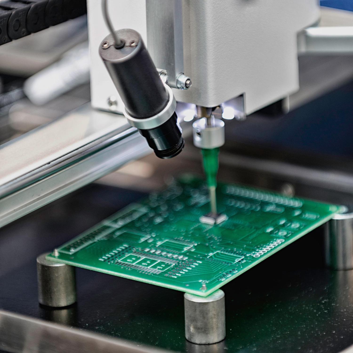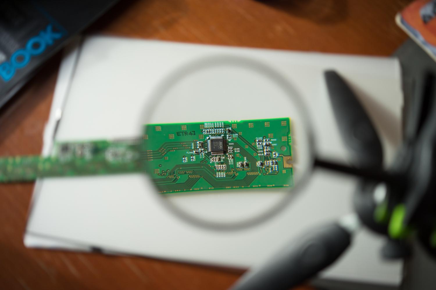
The labels 2D and 3D can make AOI selection sound like a simple technology upgrade. In practice, they describe the type of image or measurement information available to an inspection program. More information can improve a difficult check, but it can also increase acquisition time, data volume, programming, and maintenance.
A useful comparison starts with the defect or measurement requirement. If contrast, pattern, position, and visible shape answer the question, a well-designed 2D inspection may be sufficient. If height, coplanarity, volume, or three-dimensional form is essential, 3D information may provide evidence that a flat image cannot.
What 2D AOI provides
Two-dimensional AOI captures intensity and colour information across an image. With suitable lighting, it can evaluate component presence, orientation, markings, polarity, position, visible solder condition, contamination, and surface damage. Several images under different light directions may reveal more than one flat exposure.
2D methods are established, relatively straightforward to understand, and can be fast. Their limitations appear when shadows, reflections, varying board colour, or component height produce similar image patterns for good and defective conditions. A bright area indicates reflected light; it does not by itself prove a physical height.
What 3D information can add
Three-dimensional AOI estimates or measures surface height using techniques such as structured light, phase methods, multiple views, or other optical arrangements. The resulting data can support checks involving lifted leads, component height, coplanarity, solder shape, or volume where those features are visible to the sensor.
3D does not remove optical access limits. Tall components can shadow nearby areas, reflective or translucent materials may be difficult, and the available viewing geometry still matters. Measurement repeatability should be demonstrated on the real product and across the expected production environment.
Defect coverage is more important than the label
Ask a supplier to map each required defect to the image or measurement used to detect it. Some applications benefit from a combined approach: 2D information reads markings and colour while 3D data evaluates height. Other products may gain little from 3D because their critical defects are clear in controlled 2D images.
Hidden solder joints, internal voids, electrical faults, and functional behaviour remain outside normal optical coverage. The guide to PCB assembly defects AOI can detect helps separate visible checks from those requiring another method.
Operational trade-offs beyond purchase price
Compare cycle time with all required views, product changeover, program creation, debug time, calibration, cleaning, storage, network load, and review-screen usability. A more detailed result may reduce uncertainty, but only if operators can interpret it and the process can respond.
Maintenance skills also matter. Optical components need controlled condition, and measurement systems may require verification artefacts or scheduled calibration. Ask how performance is checked after service, software updates, component replacement, or a machine move.
A practical selection method
Create a sample set containing normal variation and confirmed defects. Run it repeatedly, at expected speed, on the proposed configuration. Record false accepts, false calls, measurement repeatability, review time, and features that cannot be inspected. Repeat the test after a realistic changeover rather than assessing only a carefully tuned first product.
Then compare the evidence with the full AOI systems evaluation guide. A system should be selected because it proves the required features within the production constraints, not because 3D sounds more advanced.
For mixed products, consider whether one configuration handles the full range or whether specific products need different lighting, views, or complementary tests. Document those boundaries in the acceptance criteria so that capability is not assumed later.
Review-screen evidence also deserves attention. A height map may look impressive, but operators need a clear connection between the displayed measurement and the acceptance rule. During a trial, ask several trained users to review the same findings and compare their decisions. If interpretation remains uncertain, improve the display, work instruction, classification, or inspection method before treating the result as production-ready.
Finally, consider future products without paying for undefined capability. Reserve practical space, interfaces, and support options where expansion is likely, but approve the current purchase against current samples and measurable requirements. A written upgrade path is more useful than a broad promise that the platform is future-proof.